Mars mission, strategy and code June 17, 2011
Posted by embeddedmotioncontrol in Uncategorized.add a comment
Yesterday our rover and the ones produced by other teams competed on the mars platform and demonstrated their abilities to find lakes. Unfortunately our Rover didn’t make it in the top 3, but it did manage to find one lake as you can see in the video below. This is the end of the project, and therefore it is time to publish our source code. The full source is available in a zip-file here and the most important part, the strategy, is web-viewable here.
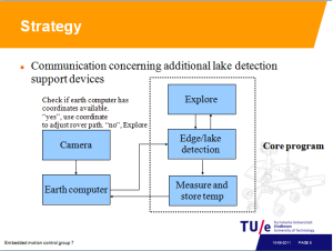
The strategy comes down to this: The rover starts in exploring mode. First it drives a little distance, then it rotates 45 degrees and waits a while, this is repeated until it has rotated 360 degrees. When it does not receive coordinates it drives a little further and scans again. When it does find coordinates at any time it rotates towards the lake using the function described in a post below, and starts driving towards the lake. If the rover gets new coordinates it does a correcting steer action and drives further towards the lake. When a lake is detected using the middle light sensor the temperature is measured and sent back to the earth computer. Of course, edge detection is always on to keep the rover from driving off an edge. When moving away from an edge the rover rotates to the right or left randomly to avoid getting stuck in an infinite loop of edge avoidance.
If the earth is not available, we create our own. June 16, 2011
Posted by embeddedmotioncontrol in Uncategorized.add a comment
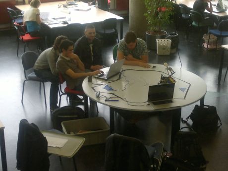
Because the last available days of testing saturated the testing opportunities on the mars platform, we decided to build our ow earth station (see picture below).
We used the simulink model, adapted it to the camera and it worked very well. This feature gave us the opportunity to test our communication between the earth station and the mars rover. Furthermore, we could check if we were on right “track” regarding the coordinate conversion from the camera to the real world. The artificial lakes were created by using original rover blue screens.
Camera Coordinate Conversion June 15, 2011
Posted by embeddedmotioncontrol in Uncategorized.add a comment
To be able to use the coordinates which are sent by the Earth computer when it has recognized a lake, the coordinates from the camera have to be converted to “real world” coordinates. A special function is designed which calculates the angle and distance of the recognized spot on the camera by using a linear conversion. The camera coordinates must be converted onto a trapezoidal grid. There was chosen to convert the camera coordinates to a steering angle and a distance as the tank-like tracks allow on spot rotation. This makes navigation a lot easier compared to making round corners, which poses more difficulties in planning a path to the lake.
At first the most distant camera-point was used to interpolate the other coordinates. After some more testing is seemed that the lens distorts the image in a non-linear way, causing the conversion to be too crude for points closer to the camera where the highest accuracy was needed. Therefore the camera was calibrated for a good conversion in the lower half (nearest/lower part of the field of view). The inaccuracy in the upper half of the camera field of view does not really pose a problem as the lakes in that region are not very often recognized by the Earth computer. As the angle still is converted correctly the error in the distance estimation is not a real problem; when Hank drives to a lake it checks its middle edge sensor to detect the lake.
2nd place linetracking! June 14, 2011
Posted by embeddedmotioncontrol in Uncategorized.add a comment
Hank became officially second at the line-tracking contest!
Measured distance 728 mm in 8 sec!
Small updates June 14, 2011
Posted by embeddedmotioncontrol in Uncategorized.add a comment
Temperature calibration update
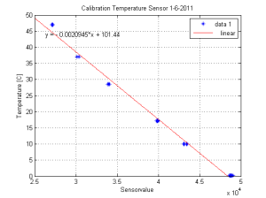
The calibration of the temperature measurement calibration has been extend with a 0 degree calibration value. This update gives us increased accuracy.
UML update
The following UML files have been updated to the current status.
Just wandering June 8, 2011
Posted by embeddedmotioncontrol in Uncategorized.add a comment
Today we sent Hank on a mars field trip, apparently he was still a bit nervous.
Houston? May 26, 2011
Posted by embeddedmotioncontrol in Uncategorized.add a comment
We have been testing with the camera and the earth computer.
The experience gained from the experiments provided us with very useful data. For communication with the earth computer we designed a program that allows us to receive the coordinates of the lakes and send it to the RCX modules, using the infrared connection.Moreover, the data acquired from the temperature sensor is send back to the earth computer.
Temperature sensor calibration May 26, 2011
Posted by embeddedmotioncontrol in Uncategorized.add a comment
One of the goals of the mars rover expedition is to acquire the temperature of the lakes. Therefore, a temperature sensor which is able to accurately measure the temperature is more than welcome. However, this requires calibration.
The sensor has been calibrated by comparing its values to those of a thermometer. For this test three cups, containing water with differing temperatures, were used. The first cup contained water of 11 degrees, the second 18 degrees and the last 48 degrees Celsius. Along with the water temperature the ambient temperature was also measured. The values produced by the sensor were plotted en visualize a linear relation. The measured data, compared to the sensor data, provided a solid foundation for our temperature approximation which is implemented in our code
Linetracker Completed May 25, 2011
Posted by embeddedmotioncontrol in Uncategorized.add a comment
Software version 3 of the last post worked fine after tuning the parameters and fixing some minor bugs. After adding support for interrupted lines our line tracker is completed. See it at work below.
Walk the Line May 20, 2011
Posted by embeddedmotioncontrol in Uncategorized.add a comment
We have nearly finished the software to make our rover follow a line, so its about time to write about how we got to it. The goal is to make the robot follow a line of any color or width on a flat surface. Also, the robot should tell us how long the line is as precise as possible. This is done in competition with other groups, the most accurate measurement is worth a case of beer, so we are doing our very best to perfect the measurement.
First off we started playing with the Lego Mindstorms light sensors our rover is equipped with. Soon we discovered that the difference between values measured on surfaces of different brightness are not that big and they depend a lot on lighting conditions, so edge detection based on an absolute threshold value cannot be used. Instead, we should look at the difference between two subsequent measurements to determine whether an edge is crossed or not.
First version
The first version of the software does just that. It uses two light sensors positioned above the surface just outside of the line. Every iteration the measured brightness value is stored so it can be used for comparison with the value measured in the next iteration. When a transition from light to dark or vice versa is detected this means that the sensor is now above the line and the robot should steer to get the sensor above the background again. This version works fairly well, but it is based on instantaneous measurements and is therefore very prone to outliers. Also, it does not make a distinction between transitions from light to dark and from dark to light. It assumes a known starting position and assumes that every edge detection is caused by the sensor moving over the line when it was over the background before or moving over the background when it was over the line before. Obviously, one false edge detection leads to the robot not knowing if the sensor is over the line or over the background any more.
Second version
The second version was a little more elegant. The sensors are moved so they are both above the line when the robot is tracking it. Before starting the program the robot is placed a little distance before the start of the line from where it starts moving. The first edge detection of either sensor is assumed to be the sensor moving over the line. The length measurement is started and the transition direction, dark to light or light to dark, is stored. Lets assume the line is lighter than the background. When both sensors are above the line, the robot moves forward. When a light to dark transition is measured, the robot applies a correcting steer action until a dark to light transition is seen. Now the robot is above the line again and can continue to move forward. When both sensors detect a light to dark transition the end of the line is detected and the measurement stops. This version of the software works nicely when the difference in brightness between the line and the background is big enough. It is however still based on instantaneous measurements, so outliers are still a problem. In practice this does not seem to be a big problem, but it leads to a compromise in iteration time. Too short and the measurement difference is not big enough leading to missed edge detections, too long and there is a risk of overcorrection.
Third version
 To deal with this problem and to be bit more robust against outliers, and also with the mars mission in mind, a third version of the program is developed. It is the same as version 2, but the edge detection works a little different. Every iteration a measurement is done and saved. Also, a moving average of the last 5 measured values is saved. After this, edge detection is performed on the moving average instead of the instantaneous value. Because the moving average climbs up slowly when a transition is encountered, the current moving average is compared to the moving average of 8 iterations ago. This makes edge detection using moving averages slower than edge detection using instantaneous values, it is always 8 iterations too late, but outliers have a much smaller impact. An outlier should be 5 times the threshold bigger than the average value to lead to an erroneous edge detection. To account for the slowness of the detector a shorter iteration time could be used, to achieve a reaction time of 400 ms like in version 2 of the software, an iteration time of 400/8=50 ms should be maintained. This version of the software is not tested on the robot yet, so if this is realistic has still to be found out. To be continued.


